Minimum width of load-bearing steel exposed behind two horizontal panels at vertical joint is approx. 127mm which could be provided by standard double steel stud configuration with steel backer plate.
Minimum bearing face for intermediate support is 42mm.
Building Basics: Lightweight steel framing (2nd edition) $45
This guide covers:
- statutory requirements
- steel framing materials
- thermal breaks
- the fabrication process
- design and erection
- roof and wall underlays
- windows and external doors
- wall claddings
- roof claddings
- insulation
- wiring and piping installation
- internal fit-out.
140mm C steel studs. Wrap in EPS to provide thermal break or Farrat Structural Thermal Breaks or Armatherm™ 500, structural thermal break material

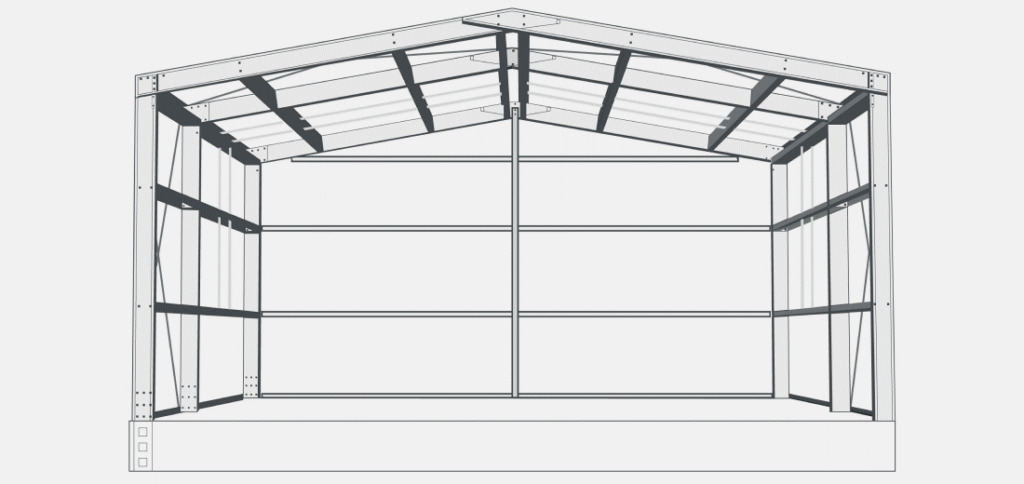
Bracketless Portal System is constructed using cold-formed flat Z450 galvanised coil.
https://coresteel.co.nz/systems/bracketless-portal/
Our system allows steel columns and rafters to be nested together and directly bolted rather than being joined with a bracket. This allows for a stronger connection between the sections.
Framing
140mm C steel studs.
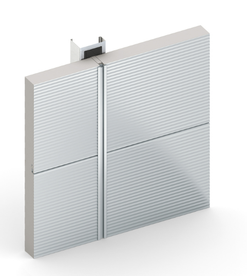
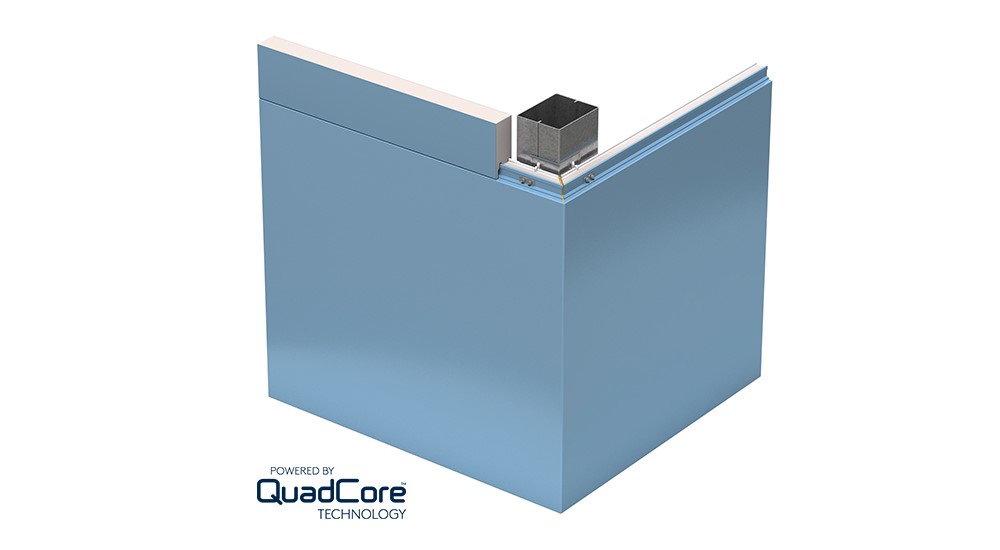
Exterior Cladding
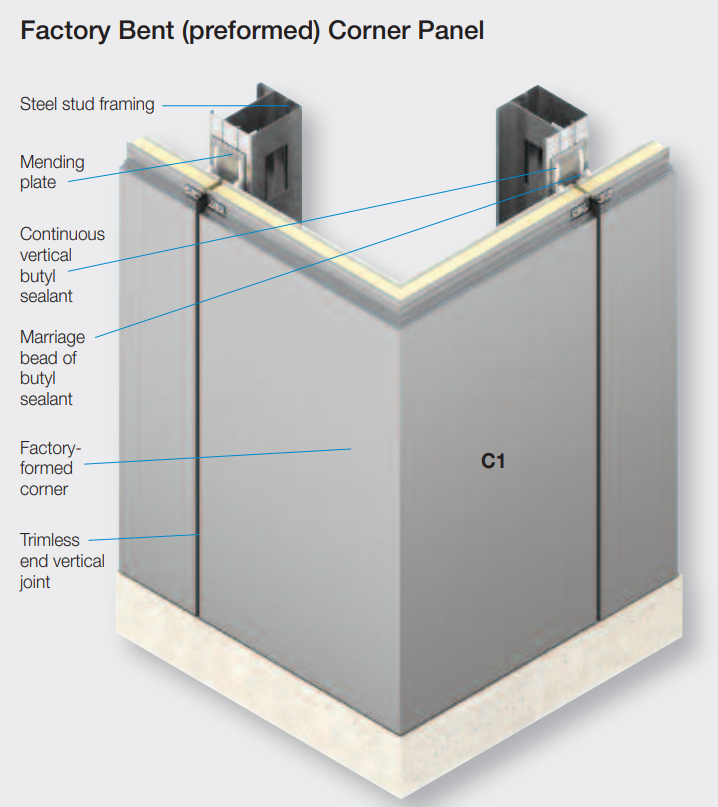
QuadCore AWP Wall Panel. Deflection limits will determine post spacing (4.8m?). Corners are 45o v-cut and folded sections of panel. Factory Folded 300mm – 3m available. If we can avoid adding a corner post by using (say) 300mm x 300mm unsupported at corner but screwed to post on each side of the house at join with end of 4.8m panels (See Kingspan ‘Factory Bent (Preformed) Corner Panel’ image below.
140mm thick 14.8-17Kg Kg/ m2 (AU)
Cover width 1m
Core Thickness options: 140mm, 200mm
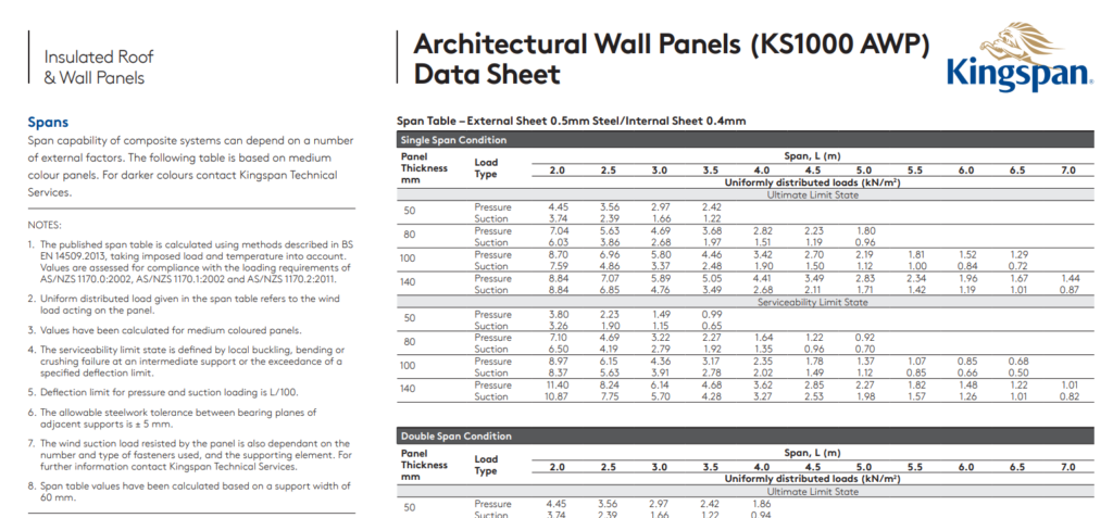
Minimum Serviceability Limit State for 150mm at 5m span cladding – Pressure 2.27 Suction 1.98
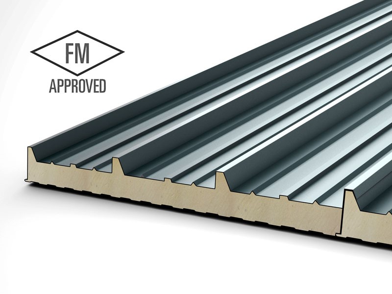
BS 8414 tested solution that has passed the requirements of BR 135 and complying with BS EN ISO 9001
Exterior Weather Sheet Substrate is 0.5mm thick Zincalume AM100/ AM150 coated steel to AS1397. Internal Liner Sheet Substrate is 0.4mm thick steel coated steel to AS1397.
For a residential building constructed according to NZS 3604:2011 Timber-framed buildings, a lightweight wall cladding is generally considered to have a mass no greater than 30 kg/m² (Ref: Wall Claddings).
kingspan.com/ca/en-ca/about-kingspan/kingspan-insulated-panels/quadcore
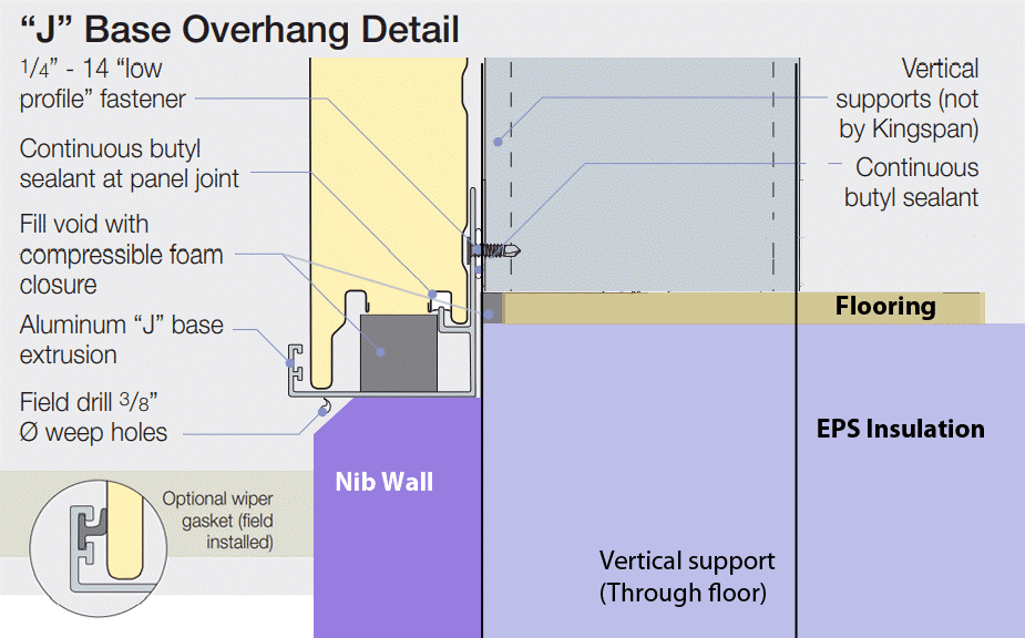
“J” Base overhang rather than flush with floor. Perhaps bead of silicone instead of wiper.
Calculate wind bracing demand
The wind zone can now be applied to calculate the wind bracing demand from NZS 3604:2011, Tables 5.5, 5.6 and 5.7. These tables give wind bracing demands (BU/m) for the subfloor structure and the walls of single and upper floors and the lower of two-storeys.
Where the zone is not high (H), the multiplier for the relevant wind zone is used to calculate the correct wind bracing demand.
Where wind zone is above extra high (from Table 5.4), the wind zone is SED or specific engineering design and is beyond the scope of NZS 3604.
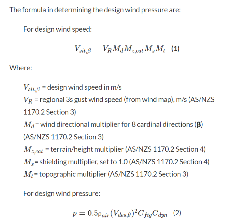
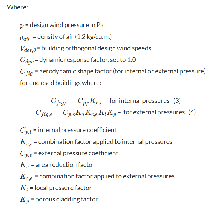
The formula in determining the design wind pressure are:
Windows
New Zealand standard NZS 1170.5
Interior Framing
Not load bearing. Steel C section single studs at 600mm centres. Plasterboard each side (10mm. Use 12mm for sound deadening if required. Laid horizontally). ezisteel.co.nz/products/140mm-wall-frames
Roof
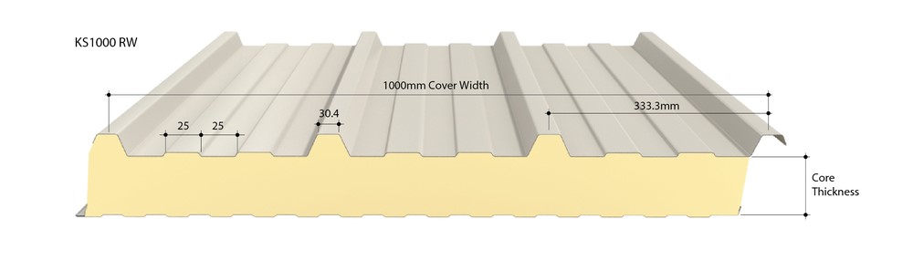
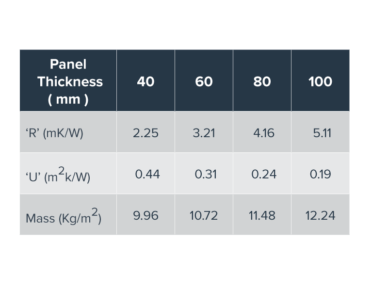
QuadCore KS1000RW Roof Panel through-fix, trapezoidal insulated roof panel, which can be used for with roof pitches of 4° or more after deflection. Trapezoidal is available in a width of 1000 mm.
Lengths from 1.8m to 29.2m. 15m is maximum practical length that can be transported easily (Up to 1m overhang allowed = 16m max.).
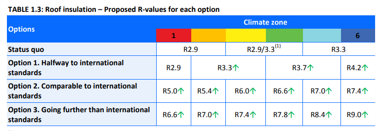
Core thickness 100mm = 0.19 U-value (R=5.35). Thermal Engineer to advise whether this needs to be thicker.
Zero overhang (No eaves). Roof rebated on underside to cover top of wall cladding, then capped with 90o flashing.
Acts as diaphragm for seismic purposes.
Fix to rafter with Liquid Nails Fuze It Max 9 oz. Interior/Exterior All Surface Construction Adhesive


Kingspan supplier:
Alternative 1 if more insulation required:
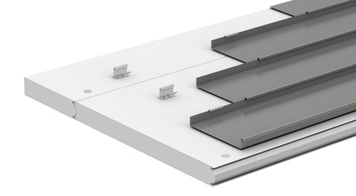
Roofliner (KS1100 RL)
kingspan.com/nz/en-nz/products/insulated-panel-systems/roof-panel-systems/roofliner-ks1100-rl
1100mm cover, white both sides. 2 degree minimum pitch. Ideal as a substrate for single-ply membrane roofs or standing seam roofs
100mm core R5.15 – Weight 14.5kg/m2, 200mm core R10.15 – Weight 18.5kg/m2
Alternative 2 if more insulation required:
Metecnospan has a PIR Core. It is a lightweight panel system incorporating a trapezoidal external roofing product manufactured in 1000mm cover panels for roof systems with a minimum pitch of 3 degrees. 100mm thickness. MetecnoSpan® is available with different inner skins.
metalcraftgroup.co.nz/products/metal-insulated-panels/products/metecnospan-pir
MetecnoPanel (PIR)
MetecnoPanel is a lightweight sandwich panel with a built in PIR fire resistant core. 100mm, 150mm, 200mm. Roofing depending on application. 11.8m maximum length
ECHOtape’s Thermal Break Tape is designed for to reduce thermal bridging on outer and inner framing in metal buildings. Used primarily in the installation of metal building panels and prefabricated wall panels, this tape is applied over the top of purlins or on girt flanges to act as a barrier or flash break between the outer shell and inner framing. This tape adheres strongly to both smooth and rough surfaces including corrugated metal. The paper release liner protects the adhesive from contaminants when the tape needs to be cut to specific lengths for use in tight spaces ensuring a strong bond once applied. FO-V2344/FO-V2348
Use ECHOtape on top of trusses.
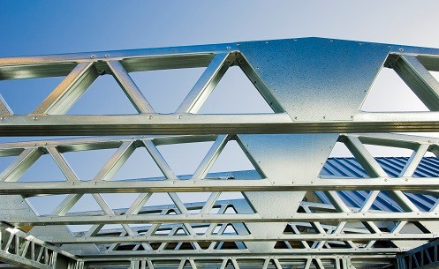
Rafters and Trusses
Cost, ease of on-site construction, low weight are the top priorities. 15m length – maximum length that can be transported. Larger building version would have a load bearing wall through the centre with a truss each side to the outer frame of the building.
Thermax B® is an acceptable solution as an economical thermal break for steel framed walls and steel framed roofs.
11m 290/1.15 @900 centres, Medium Wind Zone IL2 16-degree lightweight roof enclosed, no purlin bracing
14 gauge 200mm x 65mm roll formed C purlins back to back (To make an I beam) spans 8-9m
All gauges of section C/Z 400×30 require M16 grade 4.6 bolts. 16m single span
Vertebeam steltech.co.nz/our-products nested cold formed box sections provide excellent torsional stiffness and spanning capability.
ezisteel.co.nz/products/roof-trusses
Depending on the design of the truss, a clear roof span of 36m is achievable.
The Futura Box-Beam range starts at 150mm high with incremental increases up to 540mm futura.nz
Roof trusses are pre-fabricated to work with any roof design, pitch and roof cladding on both new and existing buildings. Designed by computer analysis, SteelHaus roof trusses and rafters are available in a variety of roof truss styles. steelhaus.co.nz/steel-framing/#roof-trusses
rollforming.co.nz/150-mm-framing
Floor
Aim for 50psf for Garage (2000Kg cars) (=50mpa, 50,000Kn/ m2 = 500Kg/sqcm)
Using high density Polystyrene (EPS) Passive Slab easily takes the weight of a 12m high block wall
The load exerted on the top surface of the floor spreads through the EPS at an approximate angle of 45o
For insulated foundations, the standard depth of hardcore under the EPS is 150 – 225mm of 18 – 35mm hardcore, compacted in layers appropriate to the compaction method.
Typical loads from a two-storey house built with standard concrete blockwork are 45 – 55 kN/m. The resulting bearing pressure on the soil under the strip footing is 58 – 68 kPa.
Insulated/Foundations/Report/Large.pdf (In folder)
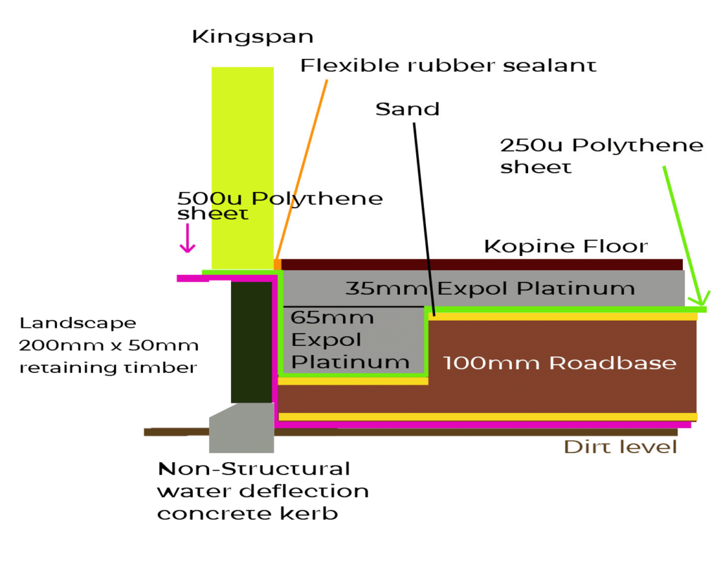
Thermathene Orange 300 micron Damp Proof Membrane (DPM) or Supercourse 500 or 1200 micron Synthetic Damp Proof Course SPC100030 (1000mm x 30m) under roadbase and 250 micron over roadbase to create dry space with constant moisture level of 7% (Optimum for roadbase compaction) to improve R value to R2. EPS on top of top membrane to prevent fastener punctures.
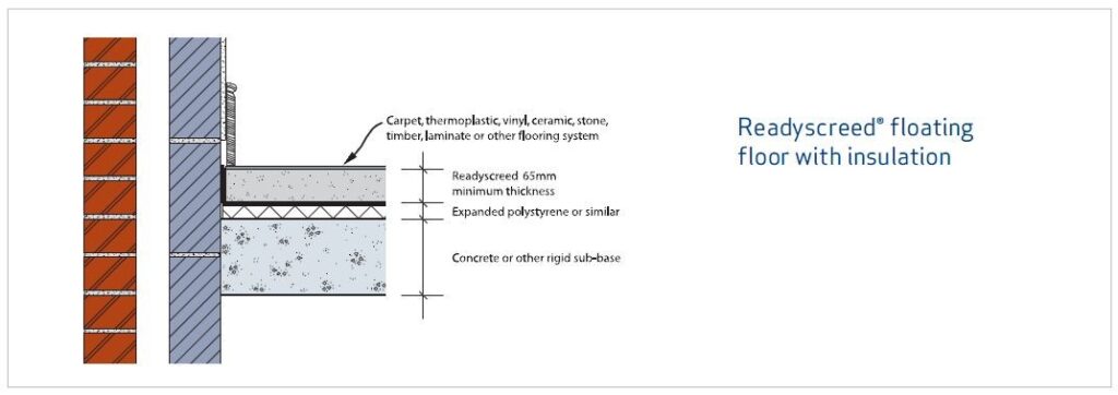
The 500G polythene membrane performs as a separating layer rather than keeping moisture out, whereas the 1200G (and above) membranes ensure that no moisture is made available to the screed and floor coverings. speed-screed.com in the UK use screed to cover underfloor heating piping. NOTE: “Concrete of other rigid sub-base” i.e. Roadbase with polystyrene on top. The screed is merely to level over the piping – it is not structural. British Standard BS8204-1:2003 (See diagram below)
Slab-On-Grade INSULATED Foundation – NO Concrete. 100mm EPS R3.3. then 2 layers of Advantec (Kopine chipboard type product) Matt Reisinger
Matt Reisinger – Montana
My proposal ‘J’ Base, Vertical framing, not drawn:
GAP65 aggregate can be placed in layers from 160 mm to 300 mm thickness. Aggregate layers should be placed in a thickness that is not less than 2.5 times the maximum size of the aggregate, but generally not greater than 300 mm thickness in a single layer. Volume = Length x Width x Thickness x Compaction factor (typically 1.3 to 1.5) – About 12 m3
Shallow foundations must be designed for the load combinations given in AS/NZS 1170 Structural design actions, as amended by Verification Method B1/VM1. Continuous perimeter foundation.
Load – 17-20Kg/m2 of wall and 12Kg/m2 of roof (Distributed load).
Nib wall/Ring beam 225mm above ground level (NZS 3604) (Interior – 20mm Kopine floor, 35mm Expol, 10mm sand, 100mm basecourse. 65mm x 450mm wide Expol for perimeter (See diagram).
250 micron (0.25mm) thick polyethylene sheet, taped joints
500 micron (0.50mm) thick polyethylene sheet, taped joints
What are Roadbases?
Roadbases are quarry materials which are used in the construction of road pavements. They are made up of a combination of coarse and fine crushed materials which, when placed and compacted at the correct moisture, form a rigid layer.
Why Supply Roadbase Materials Moist?
By adding water at the quarry, the moisture penetrates throughout the roadbase material producing a cohesive product when in transit to a site. This reduces the risk of the roadbase material segregating, ie the finer material separating from
the coarse particles.
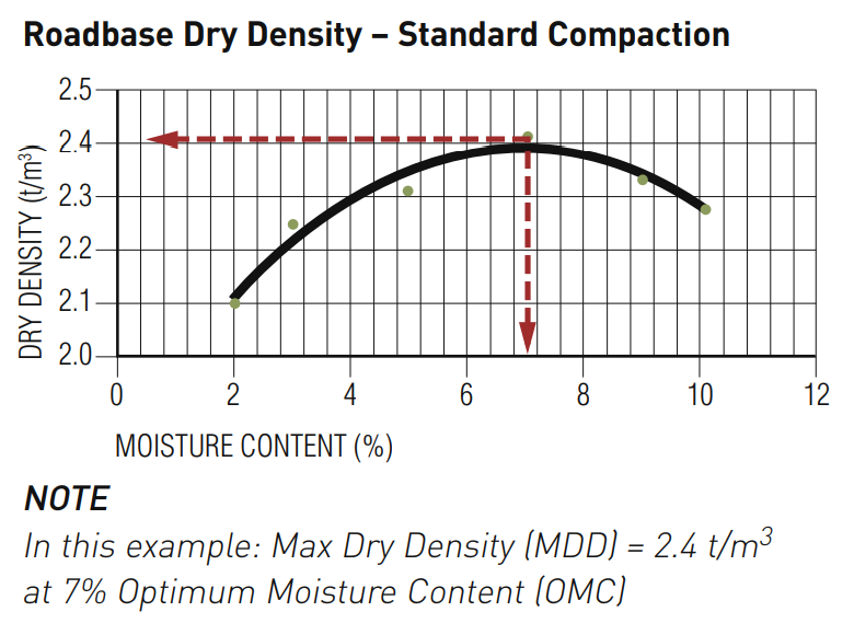
Roadbase Density/Moisture Relationship
It is the interaction of the coarse and fine particles which determines how efficiently the roadbase materials bind together after placement and compaction. Roadbase materials bind together by a combination of aggregate interlock and the plasticity of the fine materials. This binding behaviour is crucial to the roadbase performance and this occurs more readily at what is called the Optimum Moisture Content (OMC) of the roadbase material. The OMC for a roadbase is the quantity of moisture within the material which, under the application of a standard compactive effort, provides the maximum dry density that the material can achieve.
If water is added beyond the optimum moisture content, the water will occupy the extra space since there is no air volume and dry density will reduce.
Cement Concrete and Aggregates Australia website
Pressures
| kPa | Psi | |
| Human male – Standing | 55 | 8 |
| Human male – Walking | 110 | 16 |
| Passenger car | 205 | 30 |
| Adult elephant | 240 | 35 |
| Mountain bicycle | 245 | 40 |
| Truck steer tyre (3,000Kgs) | 750 | 109 |
| Stiletto heel | 3250 | 471 |
Shear Bracing Calculations
Bracing Calculation Sheets for Foundations and Walls, for use with NZS 3604:2011, October 2012
branz.co.nz/calculators-tools H1/AS1 5th Edition, H1 Schedule method, H1 Hub, Bracing calculation sheets, P21 Wall bracing test, Lintels and beams
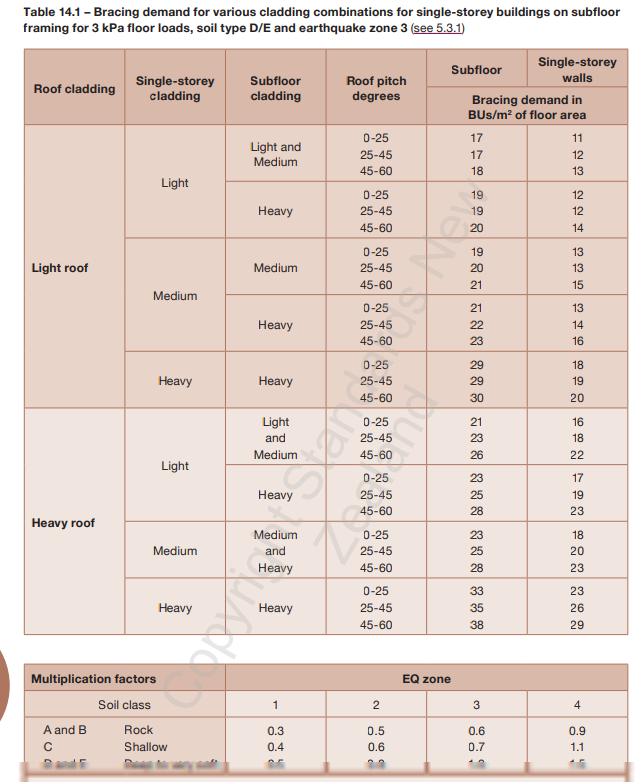
Seismic Calculations
In NZS 3604:2011, the seismic demand is determined from a predefined table, based on the soil classification, seismic hazard zone, house foundation type and building envelope weight.
Designers only need to match the bracing demand to the capacity provided. NZS 3604:2011 specifies using the P21 test developed by BRANZ to evaluate the seismic bracing capacity of proprietary light timber-framed wall elements.
However, NZS 3604:2011 has limitations on application, and many new timber-framed houses require specifically designed bracing elements, especially those with open-plan design.
Stiffness incompatibilities between different types of bracing is thought to be the most likely cause of failure variability.
Excluding the effects of liquefaction, earthquake damage to timber-framed houses was due to differential lateral deformations between either different levels or different sections within a building.
BRANZ examined the expected performance of conventional light timber-framed houses with the minimum seismic bracing required by NZS 3604:2011. This research used typical P21 rating test results of plasterboard-lined light timber-framed walls.
The displacement-based approach was followed and assumed a damping level (an indicator of energy-dissipating capacity) of 20%. The damping level was based on several P21 test results on plasterboard-sheathed light timber-framed walls.
Theory suggests light timber-framed houses with the minimum seismic bracing required by NZS 3604:2011 are likely to be flexible. They can deflect beyond the Building Code-specified deflection limit of 2.5% storey drift in an ultimate limit state earthquake event.
However, there is often unquantified stiffening potential in simple and traditional light timber-framed houses that can significantly boost their stiffness. Examples include coupling actions due to lintel beams over doors and windows, panels beneath windows and more available wall length than specified for bracing. However, these types of stiffening effects cannot be guaranteed.
Where specific bracing elements (such as steel portals) are required in a mainly light timber-framed house, they often have no significant stiffening potential. The performance criterion for designing specific bracing elements needs to include damage control.
The stiffness performance requirements for specifically engineered bracing were established to be 1% storey drift under the ultimate limit state.
To satisfy the deflection compatibility, the seismic design action at ultimate limit state of specifically designed bracing should be twice the seismic bracing demands required in NZS 3604:2011.
BRANZ has developed a step-by-step seismic design procedure for specifically designed seismic bracing elements in houses with mainly NZS 3604:2011 bracing elements.
It can be used where there is a mix of specifically designed bracing and conventional NZS 3604:2011 sheathed timber-framed wall bracing.
This will be available shortly in a BRANZ study report – Design guidance of specifically designed bracing systems in light timber framed residential buildings – from branz.